|
#1
 08-07-2006, 06:18 AM
|
|||
|
|||
|
hey,
after a few ideas with my inlet manifold and water injection points. at this point its just running a simple single stage system. injecting about 500mm before the throttle body, with 100% distilled water. manly concerned about in cylinder cooling and det suppression. but doesn't seem to be doing alot to move it away from detonation. i have tuned the car up to the point, where it gets very slight det at one point in the rev range. (listening through a detset) then switching the water on, then adding more timing. although that's about where it stops, as i can only get about 1 degree more advance at the most. am i expecting too much, or is something not quite right? have tryed diffrent size jets m2, m3, m5, with same results. except with m5 it looses a good 5hp from injection starting point till rev limit at the moment im pointing the finger towards the inlet manifold: 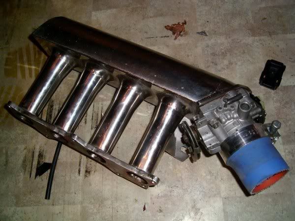 on the car: http://img.photobucket.com/albums/v1...p/Pic_0018.jpg the way the air/water is directed to the rear of the plenum, it seems the water could be completely bypassing the first cylinder. or even hitting the back to the plenum and falling out of suspense? witch would make sense, as i do get a bit of water hanging about. (all bad when the vac lines come from the bottom of the plenum, then water runs down to the ecu map sensor, when you somewhere you really don't want to break down. but that's another story :razz: ) i have thought about going to port injection. but only being 1.5L even four of the smallest jets may drown it? any ideas or suggestions would be great. kris 
|
|
#3
08-07-2006, 10:02 AM
|
|||
|
|||
|
you mean before the turbo? i thought pre comp injection had little effect on in cylinder cooling? not to keen on pre turbo injection anyway
heres a better picture of the intercooler piping. intake off turbo is missing in this pic, air filter is mounted in behind bumper in the inner guard 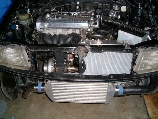 injection point is about between the + and - terminals on the battery, just after the bend. you can see in the link in my first post
|
|
#4
08-07-2006, 03:29 PM
|
|||
|
|||
|
I spose that is matter of opinion really Since the turbo is creating a lot of the heat.
How about moving it closer to the intercooler outlet. I think that the design of the inlet manifold is the main problem here TBH. What is your average inlet temp. Scott
__________________
RX7
|
|
#5
08-07-2006, 06:52 PM
|
|||
|
|||
|
Quote:
This also goes for air, as well as water mist. Assuming that fuel distribution is even, then the cylinder that gets most air will be running leaner than the rest, won't it? :wink: Ideally you'd get it on a flowbench to identify any major flaws and modify it accordingly. Usually they tend to be tapered towards the most remote cylinder (looking from the throttle) but the internal shapes make a big difference as well. It's hard to tell by simply eyeballing.
|
|
#6
08-07-2006, 09:36 PM
|
|||
|
|||
|
You have uneathed a whole problem that prob affects 90% of water injection users out there. I have a similar prob im working on. The problem is the differance of the high presure air on the outside of the bend and the low pressure on the inside in my case.
So in your case the air will flow to the farthest cylinder best and the nearest the least. This is gonna leave you short in that cylinder. Even if you have a collector which then divides into 4 you would still suffer. The main problem as far as i can see is that the manifold is designed to flow air not WI as well. You would see the prob more if you were running a AIC down stream and a egt per cylinder. I know Lotus have flow bench equipment but private work is a strict no no........ i need to ask some of the guys when im there about this....I have a better pic using my car of what your problem is. Scott
__________________
RX7
|
|
#8
09-07-2006, 01:35 AM
|
|||
|
|||
|
sdminus,JohnA thanks for your comments.
at the time i built the manifold water injection wasnt in mind at all. i think the engine should have deceased long ago if there was a major cylinder distribution problem with airflow. i dont know alot about fluid dynamic's etc, so im probably way off here.. but surely a big step down from the throttle body to the plenum. would cause a low pressure point and along with the throttle aimed to the roof of the plemum, (probably gone a bit far with the angle) would cause more of a "filling" effect, rather than aiming the air down the runners. hence no angle on the plenum. from there letting the runners/bellmouths do all the work. that was the idea, but how well it works is another question. im sure with the correct angle on the roof of the plenum it would be an advantage. but the way i see it, is if the angle is wrong, say too steep would there not be more pressure over the latter runners? no angle seemed like the best option at the time. heres a few more picures before the manifold was put together http://img.photobucket.com/albums/v1...r/runners2.jpg http://img.photobucket.com/albums/v1...r/Pic_0044.jpg anyway  but as far as water goes, it seem it could be a bit of a lost cause. water being heavyer and keeping on its merry way to the end of the plenum and not just hanging about waiting to go in like the air.. the way the runners draw in from the side not down like most oem manifolds (on top of the other problems) surely cant be helping the cause either? unsure on inlet temps, but are pretty low, out let side of intercooler never gets much past cold to touch inlet manifold doesnt get very warm either. i should test it i guess. im unsure where to go next, a reliable port injection system is almost out of my price range. maybe a jet between bellmouths between cylinder 1&2 and another between 3&4 could work? probably still not so great.. sdminus: looks like you were lucky there, you were running meth wernt you? what are your plans now?
|
|
#9
09-07-2006, 09:05 AM
|
|||
|
|||
|
This is AUDI set up:
 Cars known to have cylinder 2-3 to knock more than the rest. This is belived to be due to air distribution. This is not a problem for street car, but if you start pushing the limits of the motor you will be running in to the problem...
|
|
#10
09-07-2006, 09:07 AM
|
|||
|
|||
|
Quote:
Imagine how multiple throttle-plates are synchronised :wink: If you fit four cheap boost gauges next to each other (on a piece of MDF) and have them all connected to the intake, then a friend could be looking at them in the cabin while you are boosting on the road and tell you if they all move together. If you find runner # 1 having a few psi more than #4 then you know that you need to modify the design and try again. This could only lead to a better design that makes more power and will be more reliable under stress. Then you either blank off the holes or use them for water/meth nozzles or whatever.
|
 |
|
|


 Linear Mode

