waterinjection.info  

Go Back   waterinjection.info > Aquamist specific system Q and A and new products > Aquamist HFS-3 forum

Reply
 
Thread Tools Display Modes
  #41  
Old 02-02-2010, 10:24 PM
Richard L Richard L is offline
Manufacturer sponsor
 
Join Date: Oct 2003
Location: England
Posts: 4,936
Default

The grey harness on the HFS-3 has the wires you are looking for:

Black: Map SW0 ......... Relay N/C
White: Map SW1 (DDS3v8 MSW-1) ........... Relay COMM
Brown: Map SW2 (DDS3v8 MSW-2) ........ Relay N/O
(Relay energises immediate when gauge is switch on)

If you are using a voltage based map switch on the hydra, the HFS-3 has a dedicated wire for that, it can output 0, 5v or 8V. It can also be inverted.
__________________
Richard L
aquamist technical support
Reply With Quote
  #42  
Old 09-02-2010, 09:41 PM
gengo gengo is offline
Junior Member
 
Join Date: Jan 2010
Posts: 21
Default

What additional failsafe equipment is needed (or recommended) for those who don't have map switching available (i.e. Evo X)?
Reply With Quote
  #43  
Old 09-02-2010, 10:21 PM
Richard L Richard L is offline
Manufacturer sponsor
 
Join Date: Oct 2003
Location: England
Posts: 4,936
Default

The HFS-3 have an internal failsafe relay. It can be used to reduce boost down to wastegate presure by cutting the cable between the ECU and boost solenoid valve upon failsafe activation.
__________________
Richard L
aquamist technical support
Reply With Quote
  #44  
Old 09-02-2010, 11:23 PM
Richard L Richard L is offline
Manufacturer sponsor
 
Join Date: Oct 2003
Location: England
Posts: 4,936
Default

At present, H3 can cut one of the solenoid valves to lower boost. I believe one valve controls more boost than the other. If you want total boost drop to wastegate, you need an external double pole relay, with two dummy load resistors.

__________________
Richard L
aquamist technical support
Reply With Quote
  #45  
Old 10-02-2010, 12:11 AM
Richard L Richard L is offline
Manufacturer sponsor
 
Join Date: Oct 2003
Location: England
Posts: 4,936
Default

Preliminary HFS2/3 user manual download here.
__________________
Richard L
aquamist technical support
Reply With Quote
  #46  
Old 10-02-2010, 03:57 AM
mt057 mt057 is offline
Junior Member
 
Join Date: Oct 2009
Posts: 14
Default

In the manual a diagram show how the gain trimmer affects the slope of WI to primary IDC and it is 1:1 or 1:2, etc. It moves up and out but is not parrallel to the original idc slope now it flow mores at higher idc than it does at a lower idc or vice versa? I am trying to understands this so forgive me. Would changing the jets to a size larger be a better way to flow more but parrallel to the orginal flow pattern if high flow through out if thats desired? Or does the gain trimmer make the WI flow increase "X" percent from the trigger point parrallel to the orginal.
Reply With Quote
  #47  
Old 10-02-2010, 04:27 AM
Howerton Engineering
Guest
 
Posts: n/a
Default

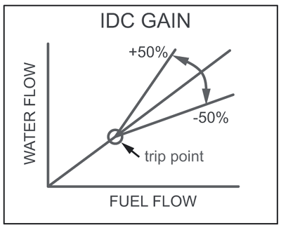
The gain trimmer will affect the slope starting at the cut-in point from my understanding. So where ever the starting point is, whether 12% or 40% or wherever, that point will start at 1:1. If the gain is left at 12 o'clock on the trimmer, the injection will follow the 1:1 slope. If the gain is turned down(to the left) the slope will pivot from the cut in point and then the slope will deviate and run shallower than the IDC slope.

Conversely, if the gain is turned up, the slope will rise, injecting more as the IDC gets higher.

http://howertonengineering.com/Aquamist_hfs3.html

Scroll to the bottom of the page and I have modified the HFS-6 trimmers worksheet for the HFS-3 control board. This should give you a visual representation of how the trimmers will affect the injection slope. You can plug numbers into the colored boxes at the top of the spreadsheet and watch the slope change. Please don't change any of the values on the other sheets as these are all the calculations to make it work.
Reply With Quote
  #48  
Old 10-02-2010, 09:49 AM
Richard L Richard L is offline
Manufacturer sponsor
 
Join Date: Oct 2003
Location: England
Posts: 4,936
Default

Quote:
Originally Posted by mt057
In the manual a diagram show how the gain trimmer affects the slope of WI to primary IDC and it is 1:1 or 1:2, etc. It moves up and out but is not parrallel to the original idc slope now it flow mores at higher idc than it does at a lower idc or vice versa? I am trying to understands this so forgive me. Would changing the jets to a size larger be a better way to flow more but parrallel to the orginal flow pattern if high flow through out if thats desired? Or does the gain trimmer make the WI flow increase "X" percent from the trigger point parrallel to the orginal.
I would like to clarify this amd update the chart.

The gain trimmer takes effect at the point of trigger. Any earlier, it will affect the trip point. If you want overall increase in flow, use multiple jets.
__________________
Richard L
aquamist technical support
Reply With Quote
  #49  
Old 10-02-2010, 09:59 AM
Richard L Richard L is offline
Manufacturer sponsor
 
Join Date: Oct 2003
Location: England
Posts: 4,936
Default

Quote:
Originally Posted by Howerton Engineering
The gain trimmer will affect the slope starting at the cut-in point from my understanding. So where ever the starting point is, whether 12% or 40% or wherever, that point will start at 1:1. If the gain is left at 12 o'clock on the trimmer, the injection will follow the 1:1 slope. If the gain is turned down(to the left) the slope will pivot from the cut in point and then the slope will deviate and run shallower than the IDC slope.

Conversely, if the gain is turned up, the slope will rise, injecting more as the IDC gets higher.

http://howertonengineering.com/Aquamist_hfs3.html

Scroll to the bottom of the page and I have modified the HFS-6 trimmers worksheet for the HFS-3 control board. This should give you a visual representation of how the trimmers will affect the injection slope. You can plug numbers into the colored boxes at the top of the spreadsheet and watch the slope change. Please don't change any of the values on the other sheets as these are all the calculations to make it work.
Jeff, thanks for making the spread sheet. It works very well. I intend to increase gain more because if the trip point is set very late, there isn't that much signal to amplify. In most cases, user will rely on the red led (<95%) to monitor the maximum gain is reached. Thje gain adjust is useful tool. Overall spray volume is governed by the jet size.
__________________
Richard L
aquamist technical support
Reply With Quote
  #50  
Old 10-02-2010, 07:41 PM
mt057 mt057 is offline
Junior Member
 
Join Date: Oct 2009
Posts: 14
Default

Thank you for your responses and that chart is pretty cool. I plan on using the same trigger point I am currently at about 30% IDC and possible up the jet size on both my jets a little. I top out currently at about 67%Idc using 4 780cc injectors. I need to check to make sure the size of my current jets.
Reply With Quote
Reply


Posting Rules
You may not post new threads
You may not post replies
You may not post attachments
You may not edit your posts

BB code is On
Smilies are On
[IMG] code is On
HTML code is Off

Forum Jump


All times are GMT +1. The time now is 03:29 PM.


Powered by vBulletin® Version 3.8.4
Copyright ©2000 - 2024, Jelsoft Enterprises Ltd.