|
#41
 06-07-2006, 08:35 AM
|
|||
|
|||
|
Thank you very much for the test performed. There is a discussion on the NASIOC forum about the effectiveness of a "pump speed controlled" WI system. Your data has helped a great deal on clarifying a few mysteries.
Driving the HSV: We do have two "peak and hold" driver for the HSV, 12V and 24V. The 12V version will not speed up the cycle time but will reduce the current to 1/4 of the origuinal value -about 250mA from 1A @12V The 24V driver will double the cycle time by about 100%, valve take 1ms to open. But there are no 24V supply on the car unless to add a voltage doubler to boost the 12V to 24V. 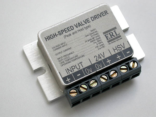
__________________
Richard L aquamist technical support 
|
|
#42
06-07-2006, 11:18 AM
|
|||
|
|||
|
Richard,
Re test ? you welcome. I will do few more to double-check. If you will do the same test at some stage it will be interesting to compare. Re HSV ? thanks for the info about the driver. I will keep it in mind. I shall comeback to the drawing board and test bench. Progress is slow as I doing these off-work hours. And there is a lot to be tested and calculated. I seem to like the idea of varying pump pressure, I may use it in conjunction with HSV. I am now waiting for samples of pressure transducers and flow meters. More I look in to it more I realize I am trying to copy fuel injection system? :roll: Just found this NASIOC forum. This is a HOT topick you run Richard  The general public need to sit down with pencil and do some calculations - they will eventially see what you are trying to tell. I guess i went thru the same process  ops: ops:
|
|
#43
07-07-2006, 12:50 AM
|
|||
|
|||
|
Well I got the chance to do some more tests.
 I am happy with the results as they much more stable and can be reproduced time and time again. I have altered hydraulics set up by relocating pressure gauge from pump to nozzle. Top graph is a relation of voltage VS flow on setup as per Richard request. Bottom graph is the same setup but with added accumulator in the system. The numbers speak for themselves. Richard I have tested 0.3 Aquamist nozzle, it flow 112cc @ 162PSI (pump with accumulator) It looks like thad by the end of the tests I will be ordering another 1-2 (0.3) nozzles from you with ?mounting sits?. As my hydraulics and motor dynamics get put together few adjustments are obvious. By the way this is how intake track looks on my car:  The runners are over 300 mm long and I plan to fit one nozzle per runner just in the beginning of it. This way water will get to travel a bit before it hits valves. Unfortunately AUDI engineers have designed the intake in such a way that the flow is violent with 120 degree turns ( towards cylinder1-2) which makes one nozzle injection useless. So the installation of ?cooling? nozzle before the throttle body is questionable as all not evaporated (and large) droplets will end up in third cylinder. Comments anyone? :roll:
|
|
#44
07-07-2006, 11:24 PM
|
|||
|
|||
|
Thank you very much for performing test. May I have a copy of the excel file as I like to converted it to duty cycle % by dividing all the V range by 12 and mulitpluy it by 10%. After I have done that, I will post it to the NASIOC board. I have just finished building a simple PWM controller today, so I can repeat the same test here using the original shurflo pump. The results are good, Pity that you can use an accumulator on a PWM pump speed WI system. It appeasr that you are now able to control the water pressure to compensate the manifold pressure change instaed of compensates it by corrected water map on the EM.
It sounds pretty good on the 0.3mm, we rate it at 745cc/min at 7 bar without surge arrestor - the aquamist pump is only a two-stroke pump with a great deal of peaks. On order to get a steady gauge reading, you can put a small ss set screws inside the hose to stop the flicker on the gauge. You're right about the intake tract. You have to use port injection. It won't hurt by putting a small jet just after the IC, it will allow the a bit more cooling along the inlet track. Droplets will be small by the time it reaches 120deg. bend. Richard
__________________
Richard L aquamist technical support
|
|
#46
10-07-2006, 10:44 PM
|
|||
|
|||
|
Quote:
It appeared that the non-linear-ness of the pressure/flow ramp again power is limited to the power of the water pump. after 3-4V ish, the pressure/flow begins to flatten out, it appeared that if a more powerful pump is used, you will get a better performace, more predictable and more linear with each addition volt fed into the pump. I could be wrong, but not able to pin point why the drop in flowrate. 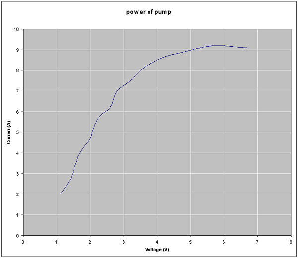 If the power of the pump can be used to product pressure rather than flow, you might have a cmpletely different flow curve. The Shurflo pump is designed for high flow with moderate pressure, you really need to look for a low flow gear pump so that you get sustainable pressure ramp. Altenatively, get a more powerful motor? Richard
__________________
Richard L aquamist technical support
|
|
#47
11-07-2006, 02:35 AM
|
|||
|
|||
|
Just a speculation here, from what I know the only pump that will have linear output is turbine/centrifugal type. From what I see plunger/piston/positive displacement pumps need torque to operate and it is not proportional to output. This is part of the pump design. Stronger motor will have the same curve but moved to the left of the graph and less powerful motor will shift it to the right ?.
Just my limited knowledge speculation? I have recived the accomulator you sent me - thank you. I may do few test later and see how it performs in comparison to my air filled accomulator. By the way, your products seem to have nice finish and good quality. I like it! Bit expencive for mass production thou.
|
|
#48
17-07-2006, 05:02 AM
|
|||
|
|||
|
Where data-logging my ECU a lot in the last few days. Now have a 3-4 weeks worth of data to analyse. The whole think is really advanced staff ? most of the data is beyond my knowledge. There are complicated relationships between air temperature, AFR, Ignition advance, Ignition correction factor and so on?..
Anyway most important for me at this stage this data:  CF = Ignition Correction Factor. Measured in degrees of timing pulled back (activated by knock sensor activity) V = knock sensor voltage (looks like amplified by factor of 10) Graph is 4-th gear pull from roll. Ambient temperature 20C, low humidity, sea-level, 98RON. ECU been fully adopted. Based on this data we will try to extract formula of CF activation. If successful we will be able to activate WI just before ECU pulls timing under the load. I also have mounted knock sensor on the engine head the other day and watched it?s performance on oscilloscope while running the motor. It?s mirrored the graph in output voltage activity with it rising as RPM rising.
|
|
#49
17-07-2006, 10:33 AM
|
|||
|
|||
|
I wonder you can resize the image to about 1000 pixels across, it may be too big for most of pur screen size.
Interesting plt. I wonder how much of the knoock signal contains backgroubd noise, it is normal for the engine to make more noise at higher RPM. I wonder if you can log a trace wthout load and compare it against the fiull load run, The difference will be a bit more representitive of the knock. I am expecting to see more know at maximum torque region rather increase with RPM. The human ear is excellent for detecting knock, may be using a stethescope to confirm the actual knock activitity charted. Richard
__________________
Richard L aquamist technical support
|
|
#50
18-07-2006, 03:34 AM
|
|||
|
|||
|
Sorry for the large plot. I will resize next time!
Richard, I found, after looking at a lot of different data logs of different people (same model car) that our engines do not seem to have the most knock during the max torque power band. This can be due to ECU been properly programmed and ignition timing been equally aggressive allowing only ?minor knock? thru out whole RPM range. Setting timing to more aggressive setting will indicate knock thru out whole RPM range unless better fuel used. It looks like ECU drives engines accurately right on the maximum timing all the time and rellies on knock sensor to stay tuned. There are only minor indications of increased CF (correction Factor) during max torque. Max torque on the stock engine is in the range 2500-3500RPM. As you suggested my next step would be to data log ?sensor noise? I will drive the motor thru whole RPM range with only 5-10% load. Then we will compare ?background noise? graph with ?full load? graph. It looks like on 2001-2006 model AUDI engines to have WI properly operating you need to inject water thru whole RPM range if your timing set to more aggressive tune.
|
 |
|
|


 Linear Mode

