|
#1
 28-01-2015, 06:56 PM
|
|||
|
|||
|
Hello,
Which wires from the HFS-4 should be connected to the Turbosmart e-Boost2 to cut boost by reverting to the wastegate spring pressure as part of the failsafe? Here is the e-Boost2 wiring diagram:  Here are the instructions from the HFS-4 manual: I was reviewing the thread at http://www.bimmerforums.com/forum/sh...r-cut-question but I am wanting specific wiring instructions for this application for clarification. Thank you! Last edited by Schultzey; 29-01-2015 at 05:00 PM. Reason: Corrected Photo 
|
|
#2
29-01-2015, 04:01 PM
|
|||
|
|||
|
You can cut the wire marked x. Splice in the grey and white wire of the Grey connector (HFS4)
You have posted a HFS6 diagram/manual instead of HFS4. Please correct before confuse others. 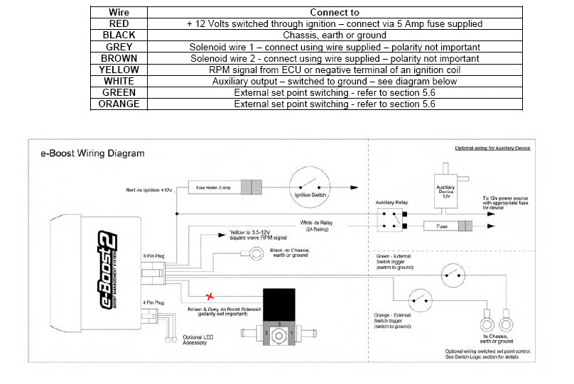
__________________
Richard L aquamist technical support
|
|
#3
29-01-2015, 05:23 PM
|
|||
|
|||
|
Quote:
To make sure I understand correctly you stating to cut and intercept one of the lines (either grey or brown since polarity is not important) going to the boost solenoid. The white HFS-4 wire of the grey ECU connector will go to the controller and the brown HFS-4 wire of the grey ECU connector will go towards the boost solenoid as displayed in example #2 of the HFS-4 manual. Is this correct?
|
|
#4
30-01-2015, 06:18 PM
|
|||
|
|||
|
Quote:
I suggest putting the HFS4's white wire to the eboost side and brown wire to the solenoid valve side. The diagram is not very easy to read. the text are too small to make sense.
__________________
Richard L aquamist technical support
|
|
#5
31-01-2015, 12:49 AM
|
|||
|
|||
|
Sorry the diagram is not clear. The picture says that the polarity does not matter. I will hook up the HFS4's white wire to the eboost side and brown wire to the solenoid valve side.
I did a little more searching and even though this set up was the HFS-6 the function of interrupting the e-Boost's solenoid wires to cut the boost is the same. http://www.bimmerforums.com/forum/sh...n-TTS2-M3-pics Thanks again!
|
|
#6
01-02-2015, 09:22 AM
|
|||
|
|||
|
Quote:
__________________
Richard L aquamist technical support
|
 |
| Tags |
| e-boost2, failsafe, hfs-4, wiring |
| Thread Tools | |
| Display Modes | |
|
|


 Linear Mode

