 |
|
#31
|
|||
|
|||
|
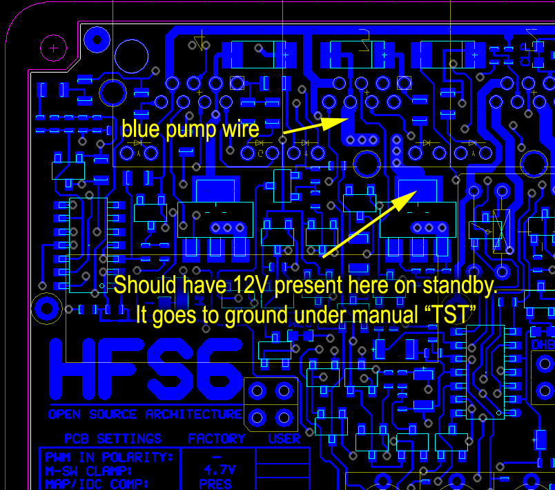
One thing to check is if the blue wire has continuity, here is how this can be done:
System on stand-by : 1. Check there is a 12V is present at the thin blue wire on the underside of the relay socket. 2. Check the RJ socket on the controller circuit board if the soldered pin has the 12V there. 3. I believe it is pin #6 (from gauge side) Anyway, do it visually as it is in blue. Let me know the result. Here is a diagram will help you with voltage measuring (relative to chassis ground). 
__________________
Richard L aquamist technical support |
|
#32
|
|||
|
|||
|
Thanks for the info. Will check today.
I've tried to re-make RJ45 connectors but this didn't help - same thing. Female connectors (sockets on board) are not good (they were not good from the beginning). When I move the conectors (any) in socket I'm loosing connection ,leds are dimming. After some time of playing with this I've managed to get green led on red connector. BUT under "TST" mode I got folloving leds lit: green - red, yellow, blue; orange - red, green (user). But as I understood, orange led should be lit for yellow connector (to ecu) as well? But not for blue - it is water level indication, right? Maybe soldering wires directly to the board will help - probably I will try this as a last chance. Anyway, system is behaving really strangely... One more thing - connectors for gauge are not colour matched (I mean they are not like stated out in instruction: red ... brown), but gauge itself seems working fine. Cable has simple wirng, not direct, but opposite, something like red is the 1st one on the one end and 8th on the other. Is this correct? Also I found a thin soldered wire connecting two transistors (outside a circuit) - should it be there? I can make a photo to make it clear what I'm talkig about. Last edited by fplucid; 25-06-2012 at 10:43 AM. |
|
#33
|
|||
|
|||
|
Things are going to get too complicated if you are going to do ten things all at once. I am not going to work with you this way. It will not get far and will waste both of our time.
First of all, every HFS-6 controller is tested individually before shipping. If you bought the system are buying second hand, this is no guarantee that it has not been handled by the previous owner. I only have your word on it. The HFS-6 was discontinued two years ago. You should not have try change the RJ45 connect without letting me first, there are a few things i need to discuss with you before hand. You have now making things a lot difficult for me to diagnose as you have introduced more variable as your effort did not yield any positive results. You know the system is way passed the 12-months warranty. I will help you if you don't do anymore DIY repairs. Can we just concentrate on the blue harness and the pump relay ONLY?
__________________
Richard L aquamist technical support |
|
#34
|
|||
|
|||
|
Richard, I repeat again that this kit was bought in sealed box, means new, from ebay. When I bought it I had no idea that it is discontinued or I can purchase it directly from manufacturer.
This kit replaced my AEM kit which was working ok, but I was recommended to change it and try aquamist. I've spend over 1k$ for purchasing, handling and shipping hfs-6 and the only thing I want is to get it work. I'm not asking for repair/exchange, because I understand this is my mistake. I can't return it to seller, because already more than 2 month passed when I'm trying to make it work. I've stated out that board has several problems, but you're reading between the lines. I'm not trying to do multiple thigs at same time, I think all of them are connected 1) there is NO ground coming to blue cable. Never. Always +12V 2) Orange led on yellow connector don't lit under TST mode (but it should according to the manual). It is only blinking accordingly to rpm, when engine is running. 3) gauge connector wire layout doesn't correspond to the one stated out in manual. Absolutely different 4) RJ45 female sockets on main board are crap. They are loosing connection all the time if you move connector a bit (same thing with oem & re-made connectors). I can't figure out which one is causing problem. Don't warry for the RJ45 connectors itself. I think I've made many more that thousands of these during my life. 5) what does this strange wire doing on PCB? should it be there? Why do such things have place on high-quality PCB?  Richard, sorry, I really don't want to argue, but I've spend huge bunch of time with this really behaving strangely thing, and I'm really pissed off. Thank you for assisting with trying to find out what the reason is, I don't want to spend a minute more trying to bring alive the kit with bugs. Topic now can be closed. |
|
#35
|
|||
|
|||
|
I am sorry that we cannot communicate effectively on solving your problem. I am happy to service your entire system at no charge if you like to return the system to me and just pay the return shipping charge
__________________
Richard L aquamist technical support |
|
#36
|
|||
|
|||
|
JFYI, main board is definately faulty.
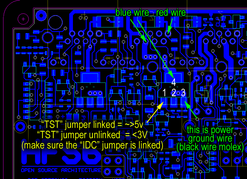
 Black connector is on 4-pin ground, red is on the mark you've pointed on above picture. Chip has 12V as well on middle leg and something like 2-3V on left and right (don't remember exactly). Is this like it should behave? On the relay itself red and blue wires are having 12V constantly. If I put ground on 6th connector pump begins to work and water is coming out. Another thing is that when I tried to swap my controller to another which is installed on EVO IX (also here, in Moscow) everything was working smoothly, even indication on the blue connector was correct. Are there any ways to solve this problem, fixing this board, or the only way is just to change it? I understand that this is not warranty case, and this is out of your interest, so I'm ready to purchase the board separately if it is possible. Can you please invoice a bill in paypal to my adress fplucid[at]gmail.com and I will proceed with payment. |
|
#37
|
|||
|
|||
|
I don't not charge minor repairs if you cover return shipping cost. Email me: richard-AT-aquamist.co.uk
We we locate aniothe rcircuit board, (v3) it will still have a link, if this is acceptable. We make links to improve the performace of the system over the interim period before moving on to the next board design. The V3 is the last version before the HFS-4 took over.
__________________
Richard L aquamist technical support |
|
#38
|
|||
|
|||
|
OK, lets have another go on this...
You are looking at the transistor that controls the pump relay. I have numbered the pins 1-4 on thre transistor. Switching function of the transistor: - Pin 1 .......... when a voltage of greater than 3V is applied, the transistor will switch on. - Pin 2/4 .......... They will go to ground when it is switched on (pump starts) by pin1. (connected to blue wire of pump relay). - Pin 3 .......... always grounded (connected to the black wire of molex). Let me know if this makes sense so far 
__________________
Richard L aquamist technical support |
|
#39
|
|||
|
|||
|
2-4 - always 12V (in normal & "TST" mode)
3 - ground, ok. 1 - normal - 0,4V, "TST" - ~1,25 So seems like there is signal coming to transistor and it is even changing, but too weak. |
|
#40
|
|||
|
|||
|
Thereare three small components below pin2 & 3. It is possible there is a dry joint there. If you carefully re-flow the solder on those components, it may solve the problem.
Let me know.
__________________
Richard L aquamist technical support |
 |
|
|