|
#1
 15-01-2013, 01:22 PM
|
|||
|
|||
|
Hello,
I'm very interested in installing an Aquamist3 system on my Smart fortwo using a 50/50 mix. I am having a hard time determining my injector sizes and therefore nozzle size. The figures I've found about my injectors(148cc/min) do not seem to be credible when compared to an injector size calculator which suggests a flow rate of around 280cc/min per injector would be required for my engine to work as it does. The 698cc engine currently runs a revised intake, filter, plumbing, bigger turbo and motorsport type exhaust and remap. Peak torque is generated at around 3500 and maximum hp is dynoed at around 97hp at 6200rpm. 3.8bar fuel regulator, Maximum boost is 1.49bar. The car is OBD II The car has a small intercooler stuffed in above the engine that relies on a small scoop and fan. It is possible to hit manifold air temps of 70C in a very short time, heat soak is a big problem. Ideally I would like to experiment with pre turbo injection with an eye to perhaps doing away with the intercooler altogether? The problem this presents is the tiny size of the turbo and being able to position a nozzle close within the tapered TIK without it being a huge obstruction; I have seen a beautiful picture on this forum of a subminature injector posted by Richard L. Perhaps I would be better off using a two jet system as evaporating everything pre turbo may be problematic, that is if I can get nozzles small enough for my meager engine? Using one post intercooler and one pre turbo but about a foot away from the turbo (some blade erossion is not a big issue as they can be changed for a lot less than the big boy's ones, lol. The goal is for a full time on boost system with fail safe and mapping and hopefully to rebuild the engine with greater compression and improved components to take maximum advantage of the injection after a more complete understanding of it has been gained. Any help welcome, please bear in mind I'm not a rocket scientist like some of you but learn quickly. Cheers! Lucian Last edited by Kapt. Q; 16-01-2013 at 08:28 AM. Reason: spelling 
|
|
#2
15-01-2013, 04:28 PM
|
|||
|
|||
|
Here's some photos of the ducting and intercooler.
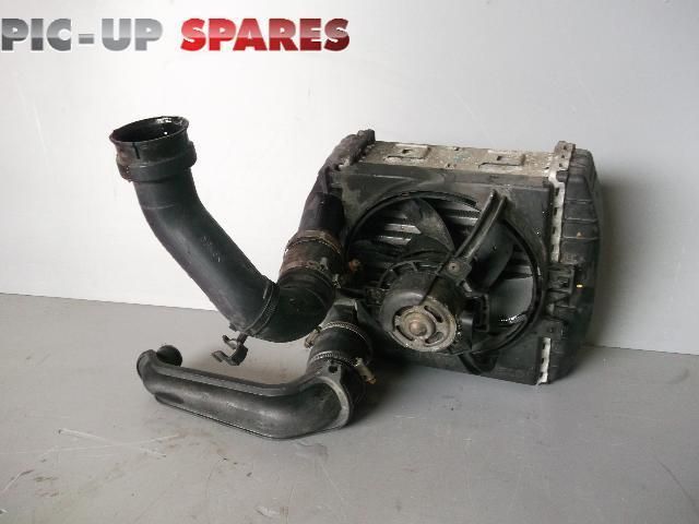 Here's the intercooler with stock ducting (replaced with silicone on mine) 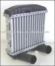 The intercooler has plastic tanks so perhaps a nozzle could be tapped into the outlet pipe. The mounting means that any condensate would collect in the plastic part of the intercooler. 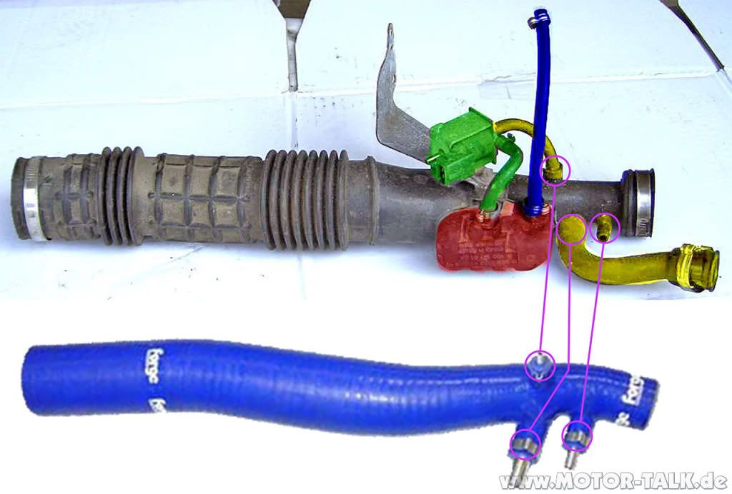 Here is the Stock TIK compared to the silicone one, the large end connects to a 90 degree bend into the filter, perhaps the best place for pre turbo injection? 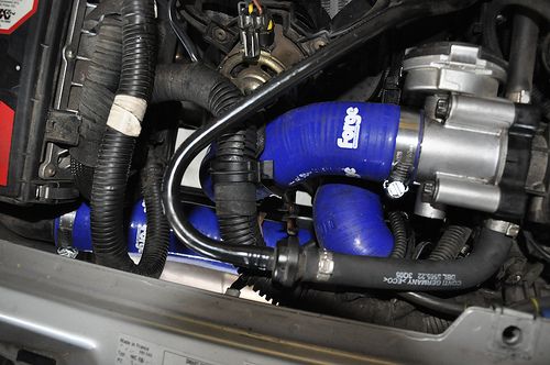 Throttle body and top of intercooler, you can only see it's fan. Forge intercooler pipes. You can also just see the blue 'TIK' below and where it connects to the airbox on the left. 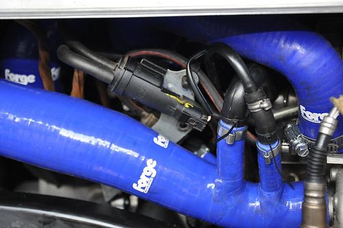 TIK connection with turbo. You can also see the first intercooler pipe exiting the turbo. Not my car, but the blue hoses show up better than black ones, you can see how tight everything is and how the intercooler is not in a good location. some people put a larger intercooler in but I think it is just buying time before heat soak at the cost of lag because there is not enough airflow to cool the one it's got let alone a bigger one. Some turbo specs, The induction side: Inlet 27mm inside bore, 32mm outside diameter. Outlet 21mm inside bore, 27mm outside diameter. Exhaust outlet Id. 40.5mm Cheers! Lucian Last edited by Kapt. Q; 17-01-2013 at 08:14 PM.
|
|
#3
15-01-2013, 04:46 PM
|
|||
|
|||
|
The 50kg's of go, 2hp for every kilo in my case!
Stock 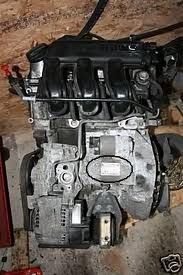 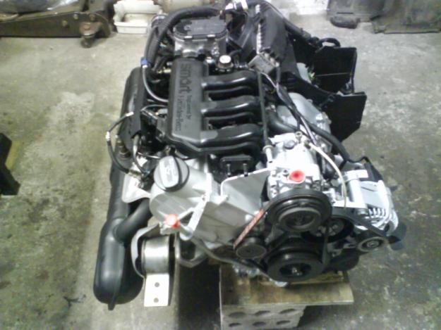 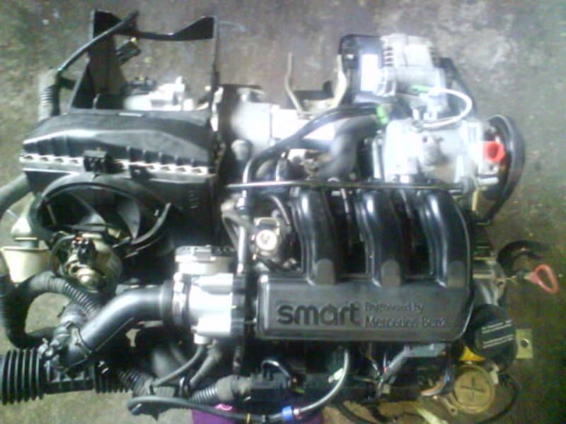 In the last one you can see some of the air ducting for the intercooler, bear in mind this is crammed in against the firewall. Last edited by Kapt. Q; 15-01-2013 at 05:19 PM.
|
|
#4
15-01-2013, 06:49 PM
|
|||
|
|||
|
Lucian,
Good grief, a lot of hard work. Very cute engine (size wise). I will make a more detail stody of this later. Thanks for posting.
__________________
Richard L aquamist technical support
|
|
#7
15-01-2013, 11:25 PM
|
|||
|
|||
|
It does have a boost solenoid.
Here's a link to a page on the setup of it, this site is the best online source for Smart info. http://www.evilution.co.uk/580 Cheers!
|
|
#8
16-01-2013, 12:10 AM
|
|||
|
|||
|
Here's some pictures of my tiny turbo, a mini Garrett, as you can see the manifold is integral to the turbine housing and it has a fast warm up channel for the cat.
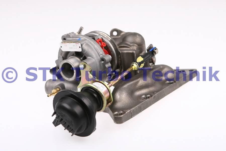 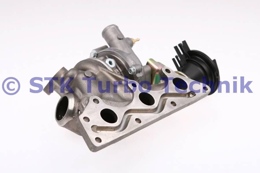 This is actually the mid range tubo for the early Smart range, some high spec Brabus used one of the same dimensions externally but with ceramic coatings on some surfaces and internal differencesalong with a watercooled chargecooler, the lower spec version has a smaller induction inlet and compressor and smaller exhaust outlet. Last edited by Kapt. Q; 10-02-2013 at 01:01 PM. Reason: error
|
|
#9
16-01-2013, 08:53 AM
|
|||
|
|||
|
Like to take it one step at a time. On the picture showing the air filter. I am a bit confused, there are several blue hoses there. Should I be looking at the hose with "FORGE" logo? To the right hand side, what is that assembly?
__________________
Richard L aquamist technical support
|
|
#10
16-01-2013, 09:51 AM
|
|||
|
|||
|
I dont have a picture with the airfilter?
The long blue 'forge' tapered hose with the three little ports is the TIK, it replaces the black plastic one in the picture, the items that have been colourised are related to the wastegate and breathers. The two intercooler pipes in some of the pictures have also been replaced with blue forge pipes too. I'll get a picture of the airbox and the 90 degree bend. Cheers!
|
 |
|
|


 Linear Mode

