|
#1
 28-01-2016, 07:49 PM
|
|||
|
|||
|
All,
I'm trying to pursue a system build for direct port injection through the intake manifold on an evo ix. I will try to document the process here. Background data:- Highest available octane at pump: 93 Oct Ambient temperatures: 32°C to 36°C Stock 4G63T long block Goals: Knock free tune @ 24psi ~320whp /310wtq I will need to install a bung in each of the runners of the intake manifold. Questions:- 1. Which system would be best suited for my application? 2. What size jet should i use for each of the runners? 3. Which specific Aluminium type bung should be used to install on the runners for the jets? 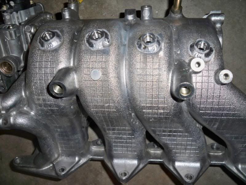 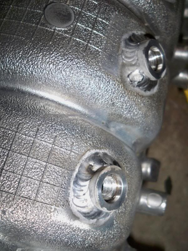  I am trying to copy that install onto the intake manifold 
|
|
#2
29-01-2016, 12:02 PM
|
|||
|
|||
 I would need the 1/8 NPT M8 jet adaptor to weld into the manifold in Aluminium. Please advise on part number / provide link... thanks
|
|
#3
29-01-2016, 06:19 PM
|
|||
|
|||
|
The jet adaptor is made of nickel plated brass, do not weld.
It is intended to be loctited in position. Here is a link of the installation steps: http://www.aquamist.co.uk/forum2/vbu...read.php?t=382
__________________
Richard L aquamist technical support
|
|
#4
29-01-2016, 08:41 PM
|
|||
|
|||
|
thank you kindly.
For the moment, i just ordered the following:- 1. M8 x 1/8NPT bungs to thread into manifold http://www.aquamist-direct.com/806-3...et-adaptors-r/ 2. 4 way hex manifold http://www.aquamist-direct.com/806-4...-hex-manifold/ 3. check valve jet for 4mm hose (806 501A 85cc/min) http://www.aquamist-direct.com/806-5...-applications/ I will offer these up on the manifold and once all goes well, i will opt for the hfs4 v3.1 system
|
|
#5
29-01-2016, 10:00 PM
|
|||
|
|||
|
Why didn't you order the direct port bundle. You will get an inline checkvalve, a 4mm connector (for the 5th jet) and 2M of 4mm PTFE hose, for less. PM me if you want to change your order.
http://www.aquamist-direct.com/806-4...ine-shop-only/
__________________
Richard L aquamist technical support
|
|
#6
30-01-2016, 01:11 PM
|
|||
|
|||
|
Thanks for the heads up.
I don't think I'd be running a 5th jet as I have a recirculating system post I/c with ti piping... -no one in country to guarantee proper drilling, tapping or fastenening of bung to ti pipe. (Trinidad) - if I put it on I/c...when it recirculates...I will introduce water droplets to the intake side /blades of turbo I will stick with original order, and build as I go along. Much thanks for the offer and guidance.
|
|
#7
20-02-2016, 10:49 PM
|
|||
|
|||
|
Loctite 271 would be sufficient for fastening the bungs to the manifold??
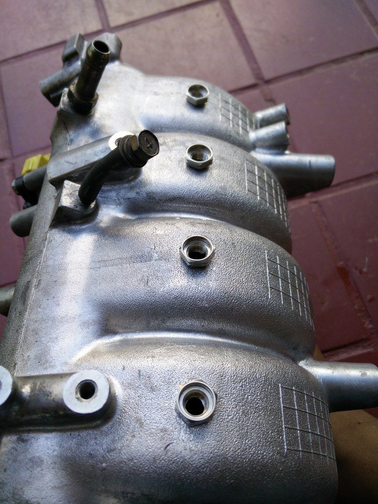 Manifold tapped and bungs installed 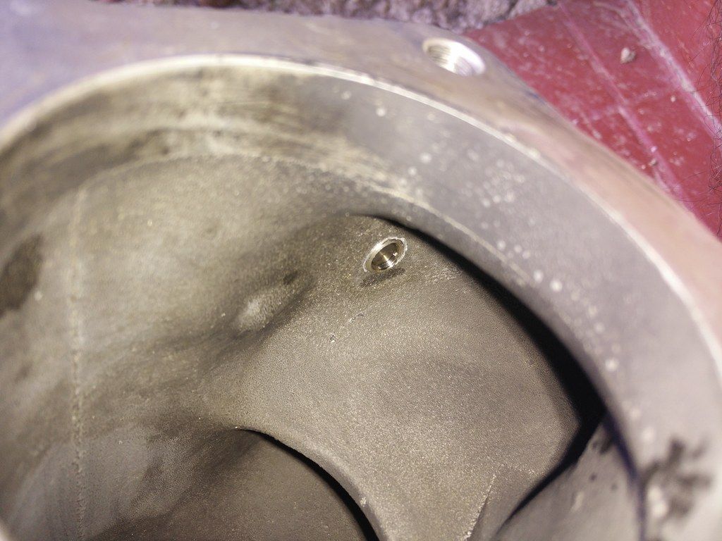 Mock up of jet in bung...slighlty recessed..no worries..(.4mm/85cc jet)
|
|
#8
23-02-2016, 05:04 PM
|
|||
|
|||
|
I would avoid placing the jets in the bend of the runners. Centrifugal forces are very high as air flow speeds can exceed 200mph.
I have found in my set-up that placing them in the straight section after the bend, close to the fuel injectors, is more efficient that the placement on top of the runner at the beginning of the bend. Less water meth had the same effect. A quick calculation showed g-forces in the order of 10000g. This is sufficient to separate droplets out of a flow stream. I would also place the jets on the top part of the runner right behind the fuel injectors and not on the bottom of the runner. The reason is that the bottom part of the flow in the runner flows across the front part of the intake valve into a smaller frontal part of the cylinder while the top part flows across the rear half of the intake valve into the "big" section of the cylinder together with the majority of the fuel. This leads IMHO to a more uniform distribution of spray in the cylinder and a better knock suppression.
|
|
#9
24-02-2016, 11:26 AM
|
|||
|
|||
|
Thanks for the advice...my thinking was to go as far as I could away from the injectors for better mixing.
It's already tapped...no turning back now ...but great info above for anyone else attempting this...
|
|
#10
27-02-2016, 01:34 PM
|
|||
|
|||
|
there is a reason port fuel injectors are usually located at the end of the runners except for very high rpm engines with short trumpets.
The mixing is less of an issue, as it is mainly done in the cylinder. you want to hit the right part of the air stream to get as much fuel into the air stream with the majority of the fuel in the top half as this is where most of the air flow happens. And you want to least amount of fuel hitting the wall of the runner and entering the cylinder as a stream of fluid in big drops. In the past with central injection and single carburated engines this was solved by heating the manifold with coolant so most of this puddles fuel would evaporate. with water, that does not work as it won't evaporate that fast and it would lose all its effect in the cylinder. for a port injection system, you want most of your spray entering the cylinder before hitting any walls or taking any bends. if you rely on evaporation of water in methanol outside of the the cylinder, you need to really go as far away as you can, e.g. the exit of the intercooler or in pre-turbo systems even to the air filter. Rice racing's set-up is a good example of this taking full advantage of the evaporation effect in the intake section before the cylinder. There is still plenty left entering the cylinder as droplets are now rather small and can take bends. So his set-up does work really well. This way as much water/meth, meth has less of an issue as it is much more volatile, can evaporate and cool. As a side effect, you end up with much smaller droplets, that have less tendency to be centrifuged out of the airstream as it takes turns. Losses from water "lost" on the walls is compensated by injecting more overall fluid. If someone cares here isa little known fact. Fluid droplet diameter decreases approximately linearly over time as they evaporate. The mass drops by time (≈diameter) cubed as volume is proportional to r^3. So to get to small droplets you need to go as far away from the engine as possible as evaporation time≈distance. Most of the mass evaporates rather fast. In the engine itself, things happen much quicker as there is a lot of heat. But still big mm sized droplets don't even evaporate there. They get blown out of the exhaust. In this simulation video you can see the evaporation dynamics. The top shows the air to water mass fraction, the bottom the droplet diameter. Past the middle of the video the steam has reached a steady state. What you can now observe is that the second half of the top stream is blue and stays blue. it means the air fraction does not change anymore, so no more water percentage / fraction is added. The bottom graph shows that droplet diameter mostly literarily decreases over time as they pass the pipe. So in the middle of the pipe they have about half the diameter (2e-5, green dots) than they have in the end (1e-5, blue dots). https://youtu.be/m9Rdu5oTrMw The second video shows a droplet evaporating. you again see that diameter drops to about half in half the evaporation time. Ethanol evaporates much faster. https://youtu.be/o1nfRcilHAI Last edited by rotrex; 27-02-2016 at 01:36 PM.
|
 |
|
|


 Linear Mode

