|
#51
 02-03-2010, 02:17 AM
|
|||
|
|||
|
Wow, looks great. I'm a big fan of the concealed install, but maintenance is always a bit tougher.
Did you do any datalogging of the original setup? We would all be interested in any changes in the data from the old setup to the new. 
|
|
#53
04-04-2010, 04:17 PM
|
|||
|
|||
|
your jets are after the iat sensor so you won't get much on that...The ecu reacts to lower iat's but in your case the only way to gain is to change the timing and rely on the knock sensors..
|
|
#54
05-04-2010, 04:27 PM
|
|||
|
|||
|
Correct. Based on a slightly lower flow to the nozzles than I was originally thinking, I may put a small nozzle in front of the IAT sensor as well to gain back the lower air temp for the sensor to see.
I'm more concerned with the actual reduction of knock, which I've had better luck with the direct-port setup for that.
|
|
#55
07-04-2010, 03:19 AM
|
|||
|
|||
|
Quote:
In theory you should have a nozzle about half of all the nozzles in the runners, at the throttle body you have all the flow for the whole motor so having a nozzle the same size as the ones in the ports will prob not be enough..My ideea bbut the aquamist gurus can prob give a better answer
|
|
#56
06-04-2011, 07:16 AM
|
|||
|
|||
|
full (stealth) engine bay install, 05 legacy gt:
started with heavy corner brace for pump mount (several used, custom bends) 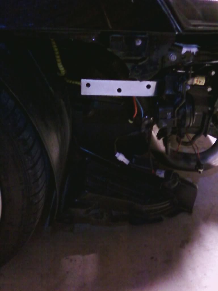 pump installed (vertical orientation. everything loomed. all water lines run through bumper beam) 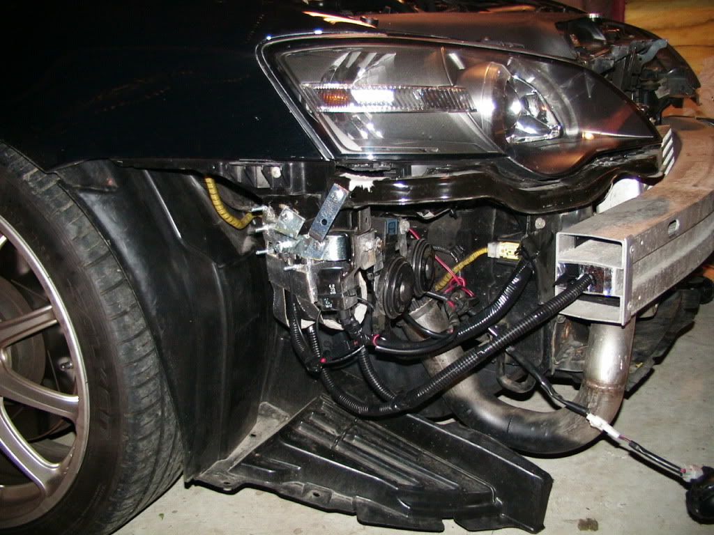 oem washer tank used (have since switched to all compression fittings) 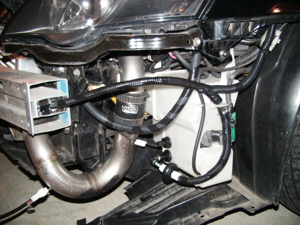 only fcm visible in bay (on fuse box) 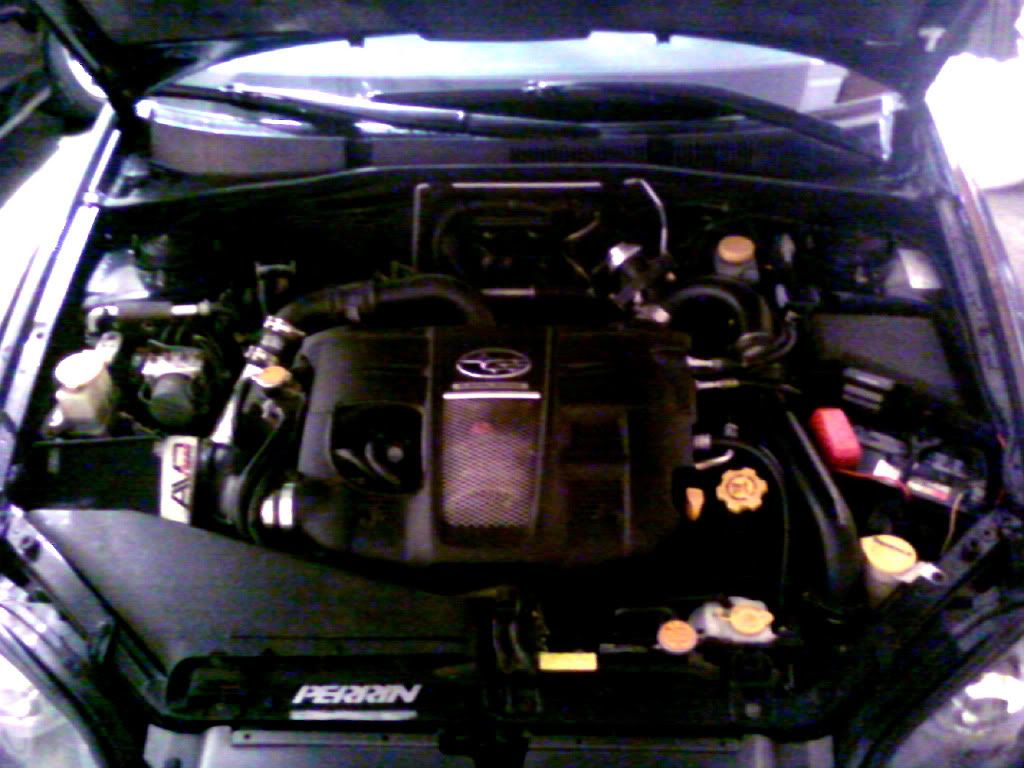 typical glove box home for controller (industrial velcro on bottom of case) 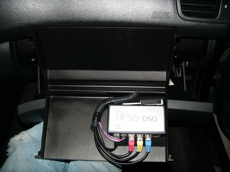 gauge in cubby 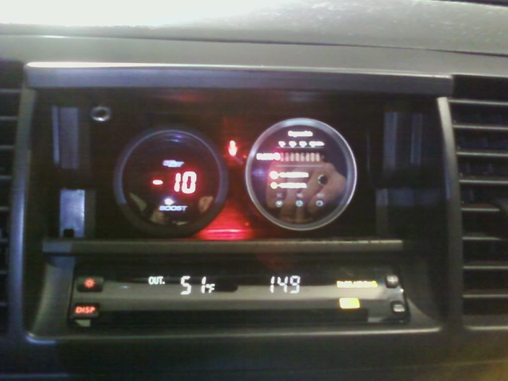 with this setup since my early order of hfs-6 debut  thanks to richard for all his support.
|
|
#57
07-04-2011, 06:56 PM
|
|||
|
|||
|
Thanks for the pics, good place for the gauge!
beware of water splash to the pump, the aquatec pump does not like dampness. It must have taken you some time to haver the sytem installed as I can see the system is an eariler version. Better late than never. Are you getting the car tuned?
__________________
Richard L aquamist technical support
|
|
#58
09-04-2011, 09:40 PM
|
|||
|
|||
|
yes, i ordered just when the system came out; install took a few weeks to carefully consider configuration options and ultimately map all out in my head, and a few days to actually tackle.
but i have been spraying hfs-6 in this config since then (for about 2 years?), so i have confidence in the way all is situated. you've actually helped me a lot through email/phone/mail with some odds and ends over all this time (Rob)i just recently found this forum, decided to post the old install pics up. car was tuned on dynapack with pe1820 a few weeks after install (i didn't bother asking for numbers/sheet, it is an automatic). same setup to this day, ~22 psi, very torquey on the spray. i've laid a thin bead of rtv silicone at some of the pump seams/wire entry to help protect from water (all factory splash guards are in place, as well), and incorporated a bit of rubber spacers in the bracing to protect from vibration/jarring. Last edited by underpowerd; 10-04-2011 at 10:03 AM.
|
|
#59
30-04-2011, 12:41 AM
|
|||
|
|||
|
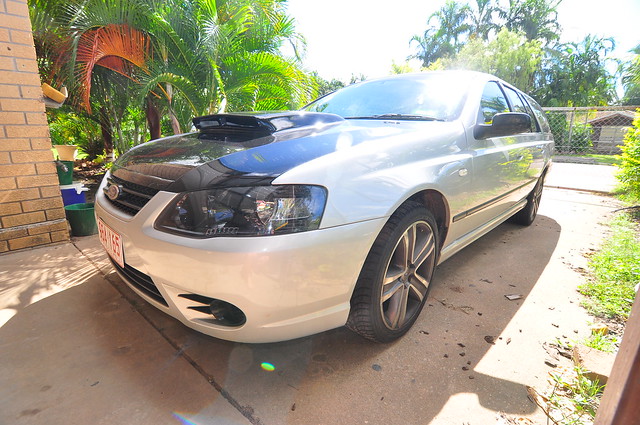
Firstly-The wagon in all its ugly ducklingness. Still to be lowered, paint incomplete....but it gets to the shops pretty quick
 A very dirty engine bay 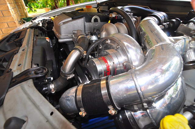 I have a Raptor typre R hybrid sidewinder bolted on. It's not making near the power it should be yet, it also needs a decent tune. Have an intercooler I need to install before the tune happens though. As well as nutting out HFS-6 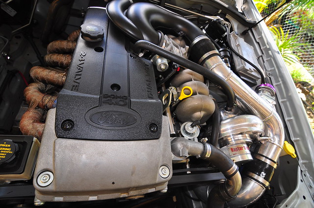 Here is the control module temporarily residing in the tissue box holder. Once the whole lot is tuned and totally installed i'll tuck it away behind the dash probably. Though it's good to be able to see the lights working for data transfer so you know things are working. Not real keen on the messy cables though..... 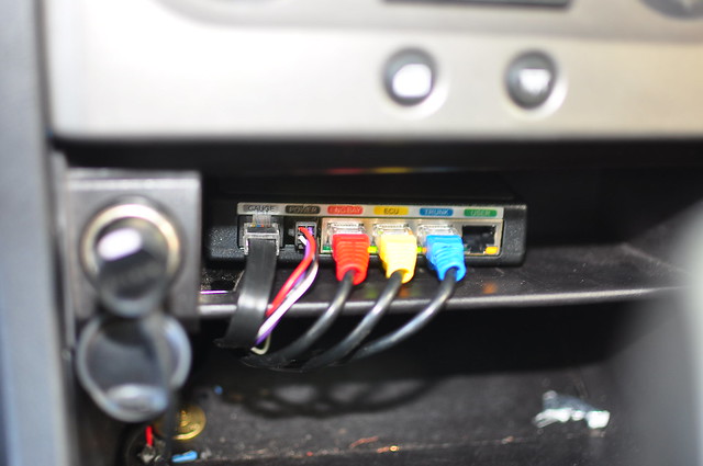 Gauge cluster with temp guage still to come. I haven't been able to find anything I really like the look of as yet.....Though the boost gauge doesn't do much for me either. Rather get some cobalt ones I think, though was in a rush and got what was cheap. 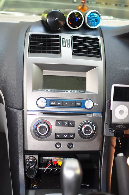 From the flow control module into the intake piping. I think two big jets is probably overkill for this application. Still need to work out what size jets to put in. 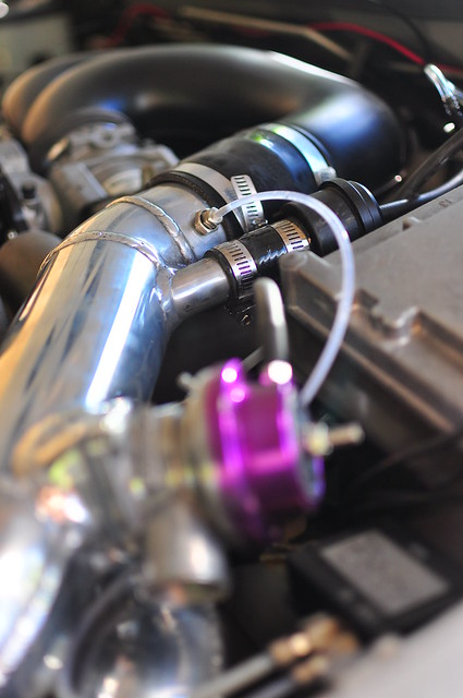 Flow control 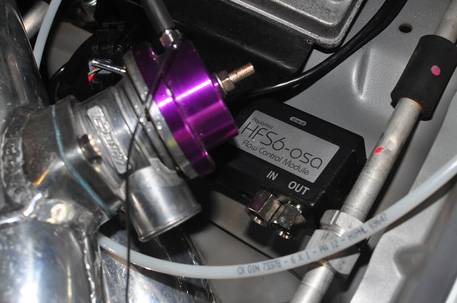 And finally the second position which is currently blanked off. 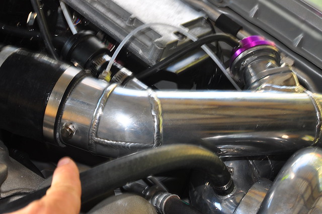 I have a 200X200X600 temporary tank that resides in the back of the wagon until the permenant one gets made up. The permenant tank will be about 1200mm long and 80X140, running the whole length of the rear bumper tucked in behind it, totally out of sight. I have the pump etc installed under the rear bumper as well. I welded in a 6mm steel plate to the chassis and screwed it to that. All the cables from front to rear of vehicle are running through the floor pan, except the hose which runs underneath vehicle, then inside the sideskirt before coming up inside front wheel arch. Wasn't keen to run fluid through the vehicle.
|
|
#60
01-05-2011, 06:37 AM
|
|||
|
|||
|
^sharp car and looks like a nice install. one thing i'd do is put some loom on those water lines, especially in the engine bay.
|
 |
|
|


 Linear Mode

