|
#241
 13-08-2005, 08:12 PM
|
|||
|
|||
|
Yeah, teardrop profile, that would be ideal (tears of joy :lol: )

|
|
#242
13-08-2005, 09:39 PM
|
|||
|
|||
|
Just my 2 cents. This will be a significant restriction, with air moving over it at over 100 mph. I see a possible flow issue. I would taper each side to a V.
Also, if it is possible to integrate the mount, such that no cross sectional area is lost at that location (larger diameter chamber that flairs back to normal) that might mitigate head loss.
__________________
Michael Patton (aka Killerbee)
|
|
#243
13-08-2005, 09:59 PM
|
|||
|
|||
|
Which "side" are you referring to?
The ID of the fitting is the same as the ID of the turbo flange. Just sized the images after anodising. You should be able to see the sides better. 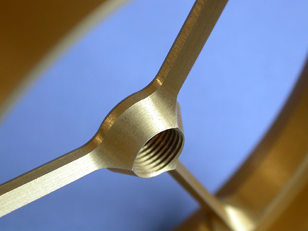 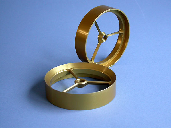
__________________
Richard L aquamist technical support
|
|
#244
13-08-2005, 10:44 PM
|
|||
|
|||
|
When airflow gets to the fitting, it will either have the additional obstacle (restriction) to overcome.
That pic looks nice, a sharp V on the fins, if the backside tapers back to a V the same way, good job. I would just "round" the transition, instead of the flatspot or angle change. If you like, you can widen the fins, in the effort to make them as thin as practical, the idea being invisible to the airstream. With respect to the ID of the fitting, if you can enlargen it just a bit, in a blended curvature, so that no x-sectional area is lost (from the addition of this beautiful cut piece) that will help minimize head loss as a suction side restriction (the worst kind). The last thing you want is a failure due to cavitation. that is what I fear. And larger diameter, at the fin location, may help.
__________________
Michael Patton (aka Killerbee)
|
|
#245
13-08-2005, 11:04 PM
|
|||
|
|||
|
Thanks for the advice and useful suggestions. I will thicken up the fins for the next time but will do for the time being.
At present the holder ID is identical with the turbo flange ID. See picture below. There are no breaks - red circle. As far as the air is concern, it cannot see the gap at the intersection. The chamfer on the OD is gone on the anodised version. I will also round off the tapered fin to minimise any notch developing. It is knife sharp at the moment. 
__________________
Richard L aquamist technical support
|
|
#247
13-08-2005, 11:16 PM
|
|||
|
|||
|
I will report the results as soon as I have it. I am keep my fingers crossed and hope the fins hold up. I cannot not rob any more machine room time anymore.
__________________
Richard L aquamist technical support
|
|
#248
14-08-2005, 12:22 AM
|
|||
|
|||
|
That's a beautiful piece of machining and I look forward to hearing how well it works. As a non-turbo user this is the first time I've looked at the insides of a turbo this closely. It looks as if there is an abrupt contraction just downstream of your new fitting. Is that real, or is it an optical illusion? If it's real I imagine it's there for a reason but I can't see what the reason would be.
__________________
Peter Humphries (and a green V8S)
|
|
#249
14-08-2005, 08:58 AM
|
|||
|
|||
|
that does look fantastic. just wondering about the water feed pipe.
how do you get those small filters in the jets? do you screw the barbed pipe part into the base? if you did, could you then machine a thread onto the turbo side of the plate, and screw the jet onto it. so you would have a thread on the outside of here.. and a cone on the other side to help flow. then machine a hole into one of the fins to get the water to the jet. if you see what i mean? Drew
|
|
#250
27-08-2005, 12:55 AM
|
|||
|
|||
|
The water will be channeled into the jet via the rails, possible redesigned the jet jet to accept water on the side, similar arrangement as the side inlet fuel injectors.
The tail of the jet will be a cone shaped nut, as described by you.
__________________
Richard L aquamist technical support
|
 |
| Thread Tools | |
| Display Modes | |
|
|


 Linear Mode

