 |
|
#1
|
|||
|
|||
|
Hello everyone, long time lurker, first time poster. I have a fast question regarding my .4mm check valve jets...
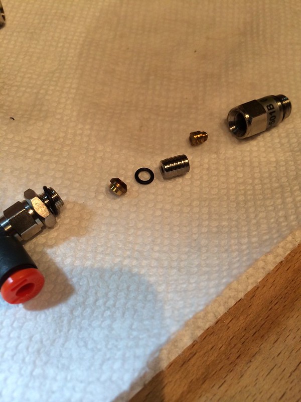
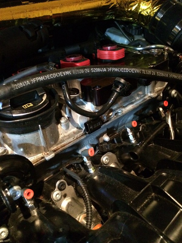
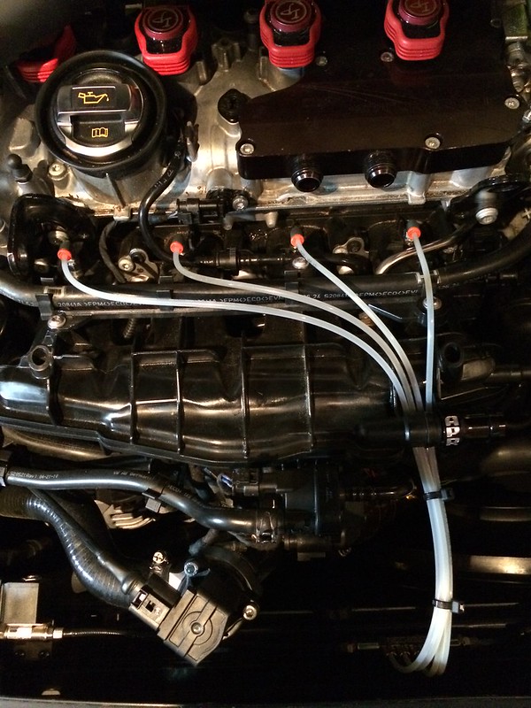
-I converted my intake manifold jets to the 90 degree push lock fittings, before re-installing them I soaked them in warm water with alcohol to clean any debris from the first tank full of water methanol. In doing so, one of the CV jets came apart completely. Can you tell me if I have the correct reassembly orientation in the attached photo? Does anyone have a picture or diagram of the correct CV jet assembly I can reference? I want to make sure I have it re-assembled correctly as my software tune relies on equal flow rates. -Can anyone tell me how to verify what flow rate these .4mm CV jets have? Are there different options for the flow rate within a .4mm CV jet (ie 90cc, 110cc, etc)? Is there a way to rebuild the jet to change the flow (add more flow) so I don?t need to buy all new jets? Thank you everyone!     |
|
#2
|
|||
|
|||
|
The flow of the jet is determined by two components
1. The depth of the groove on the internal spinner 2. The size of the orifice. They need to be matched if optimum performance is required.
__________________
Richard L aquamist technical support |
 |
|
|