 |
|
|
|
#1
|
|||
|
|||
|
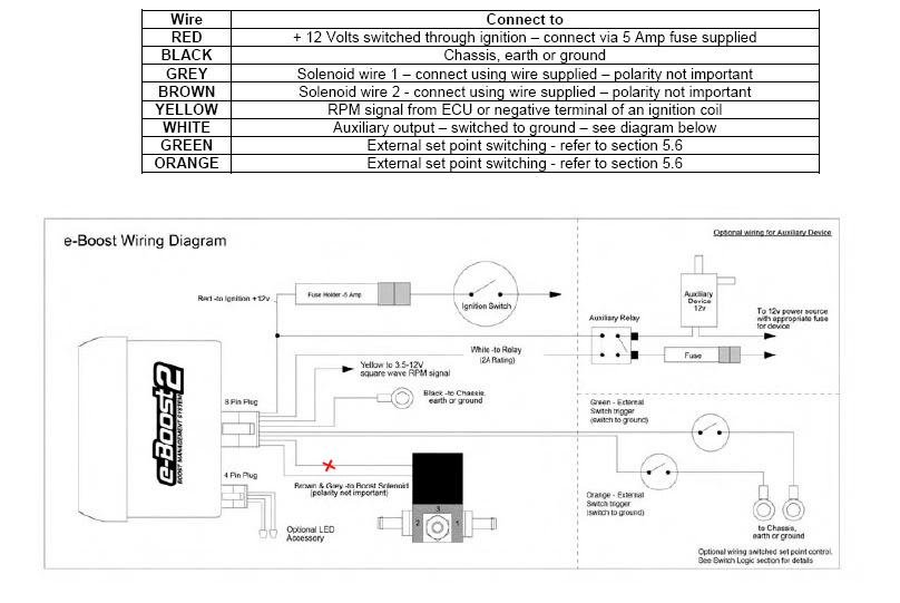
You can cut the wire marked x. Splice in the grey and white wire of the Grey connector (HFS4)
You have posted a HFS6 diagram/manual instead of HFS4. Please correct before confuse others. 
__________________
Richard L aquamist technical support |
|
#2
|
|||
|
|||
|
Quote:
To make sure I understand correctly you stating to cut and intercept one of the lines (either grey or brown since polarity is not important) going to the boost solenoid. The white HFS-4 wire of the grey ECU connector will go to the controller and the brown HFS-4 wire of the grey ECU connector will go towards the boost solenoid as displayed in example #2 of the HFS-4 manual. Is this correct? |
|
#3
|
|||
|
|||
|
Quote:
I suggest putting the HFS4's white wire to the eboost side and brown wire to the solenoid valve side. The diagram is not very easy to read. the text are too small to make sense.
__________________
Richard L aquamist technical support |
 |
| Tags |
| e-boost2, failsafe, hfs-4, wiring |
|
|